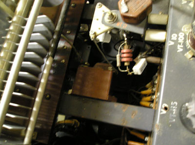
The bias of the 250TH is composed of 1. Self Bias and 2. Fixed Bias
1. - The fixed bias resistor (R11) should be set for -110VDC , measure at bottom of CH8 with Exciter only turned on.
2. - The "self bias" is produced by the biasing resistor added at bottom of CH8. I use about 470 ohms, 10w resistor. This should give about -180VDC bias when in Phone position.....CAUTION.... be careful when measuring the bias voltage as the HV must be on. Connect Volt Meter leads before HV is on and keep hands out of the top rack!!
With -180VDc bias and enough drive you should see about 400W to 500W output on 160m (when using the home made 160m coil) and 75M in Phone position ( 2000 V). You may have less than 500W out on 40M and 20M.

Note: The resistor across the RFC ( CH-8) is to dampen any parasitics in the RFC..... I now use two 100K, 3W carbon composite in series ( 200k) instead of the metal film resistor shown in the picture....the metal film resistor did not hold up.
If drive is still low...try solid stating V12 also C16 and C17 may be increased. Make sure new caps have a high enough DC voltage rating.
While working on the Bias voltage visually check the voltage regulator tubes, they must "fire" to achieve max drive.
This Web Page Created with PageBreeze Free HTML Editor