
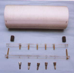
The BC-610 160 meter coils are very hard to find and if you do find one chances are it will be deteriorated. If one does not mind not being totally ōstockö a excellent coil can be fabricated for very little money. Some PVC tubing, a pound of # 14 enameled magnetic wire, two pieces of plexiglass a few brass machine screws and some of the old parts from a BC-610 coil are all you need.
Parts list:
1. About 10 Įö PVC white pipe ╝ö wall thickness, 3 Įö OD (standard 3ö ID) finished coil is 9ö long
2. Two pieces Plexiglass ╝ö x 5/8ö x 9ölong
3. Six #16-14 crimp and solder lugs (2-4L with 3/16ö hole)
4. Two pieces wood dowel Įö dia. x Šölong.
5. Two brass machine screws #6 x 1 Įö
6. Five brass machine screws #6 x Šö.
7. Five banana plugs from a old BC-610 coil.
The first part may be the hardest, as you must have access to a lathe.
John W1LZY turned a wood form for the PVC pipe to fit over and then ( see next pic) secured the PVC to it with a screw then cut the threads with a .070ö wide tool and cut to a depth of .050ö making a nice groove for the #14 enameled wire to fit into.
Using some 3ö ID PVC (3 Įö OD) white pipe with ╝ö wall thickness to make the coil form. Use about 10 Įö for the blank to be turned with 10 turns per inch. The finished length is 9ö with threads the full length.

Next....After cutting the PVC form to 9ö length two flats were milled on each end giving a flat surface to mount the support bar
-----------------------------------------------------------------
Drilling the support bar.
The support bar is made from two ╝ö x 5/8ö x 9ö strips of Plexiglas. File all edges smooth. Tape the two pieces together securely then lay out and drill the mounting and the banana plug holes. Drill the center hole first and secure with a screw to hold the pieces in alignment. Note - all holes are referenced to the center hole, center to center.
Use a 9/64ö drill to drill all holes¢ find center of 9ö bar and mark for center hole, mark out two holes each side of center 1 ╝öapart and 1 1/4" from center[ see pictures] these are the five banana plug holes.
Mark the bar for the two mounting holes; they are 8 Įö apart and 4 ╝öeach side of the center hole.
---------------------------------------------------------------------
Drilling holes in the PVC form for wire and mounts.

Use a 1/8öor 9/64ö drill for the holes. Here we have 2 rows of holes with 6 holes in each row and the distance between holes is measured by turns or grooves. Start by finding the center of the 9ö coil form. Draw a line from end to end of form; this is the center line only. Now draw lines parallel and ĮÆ each side of this center line. We will drill holes on this line for the wire to enter and exit the form. Drill all the wire holes in the groove were the wire would lay.
Find center groove of form. Count 4 turns each side of center groove(this will be the 8 turn center link) mark the groove on the lines parallel to the center line (2 marks each side). These holes are to hold the wire for the center link
From these marks count 3 grooves and make 2 more marks for holes for the wire. Do for both sides. Follow the picture.
From these marks count 32 grooves and make 2 more marks on each side.
You now have a total of 12 marks, 6 on each line parallel to the center line.
Lay the bar over the center line, mark and drill the mounting holes, one on each end of form and on the center line.
Now with all the pieces ready we can begin winding the coil.......
---------------------------------------------------
Winding the coil
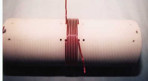
Note: The wire is held securely in place by using the 2 holes, this will make a neat and tight coil.
Wind the center link first. It is 8 turns with 3 turns spacing from each end winding. Use needle nose pliers to feed wire through drilled holes. Leave about 3ö tails for connecting to the banana plugs.

Continue winding the 32 turn sections. Wind from center out to ends, keep wire tight and kink free.
When all windings are complete we will begin to assemble the coil......solder on the wire lugs, try to keep leads no longer than necessary to connect to the banana plugs and the bar. After coil is wound test fit the mounting bar and cut wire ends to length. Use only brass or nickel coated brass hard ware.

---------------------------------------------------------------------
Using the coil:
To achieve the proper loading into the antenna tuner I use this circuit. Rotating C1 will have the same effect as rotating the center link in the stock 160m BC-610 coil.

C2- is a transmitting capacitor RF type mica and must be capable of carrying the RF current ( about 3 amps.) see picture below.
Values are not critical for C1 and C2 but these should work. Use a variable cap with more spacing than a BC type cap.
This is what I use
C1 -is a Valiant transmitter variable loading cap or equivalent, about 20 - 250pf.
------------------------------

C1 & C2 are mounted at the RF output on the transmitter, between the coil and the side panel, with the variable cap shaft protruding from the side.
I use a 52 ohm connector to attach the coax to the output.
With the correct value of C2 the C1 variable cap can vary the loading from 200ma to 300+ ma. on 160m.
C1&C2 will not effect loading on other bands.
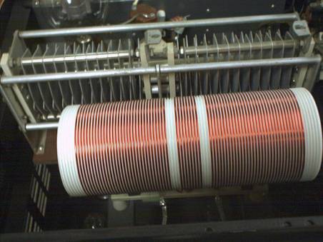
Finished coil mounted in the BC-610E ------------------------------------------------------
This Web Page Created with page breeze Free HTML Editor